The different prototypes of Rookie drive
#1, The first prototype
Here we go!!, for rapid prototyping I used the rear bus output of the HX-10, 50-pin connector, to which I wired the address comparator and the ch376s, the eprom mounted on a cartridge plate in the top slot (pictured the cartridge with the eprom is out of the MSX, but it is actually in the slot)
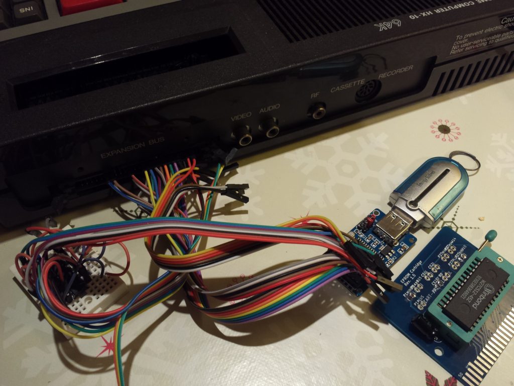
My first tests were in from MSX Basic, simple things, detect the device, mount the unit, etc. From there, the assembler, the best way to learn … This is my first project in assembler. I spent a few hours until it worked, at first I used a fixed disk image named HE.DSK, (for highway encounter), but it was boring, if I wanted to change games I had to connect the pendrive to the PC and change the image for another…
Unsatisfied at the moment, I soon got to work and create specific “CALL” commands to handle the device with ease. This time I was able to get some information about the glorious MSX.ORG page, in its wiki there is a section dedicated to the “CALL” command
So here is the list of “calls”
- createdisk
- insertdisk(“image name”)
- eject
- usbfiles
- mount
- help
See details of features here
Then every time I turn on the computer I have to “insert” the disk by hand, so create the file “USBMSX.INI”, which keeps the name of the last disk inserted, now when the computer is power on, it loads automatically (if you have autoexec) the last used image.
Of course, this is cool, but in the end it’s tiring if you have to give CTRL + STOP, assuming BASIC is loaded, so I implemented the option to abort automatic insertion by pressing the ESC key when starting the computer.
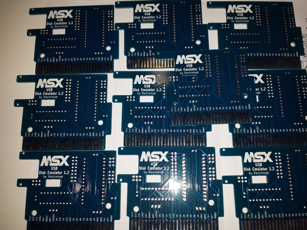
At some point in the development I started to design with Kicad, so I have made some prototypes on PCB with pcbway, I am impatient to receive them ..
#2, The prototype of the impatient
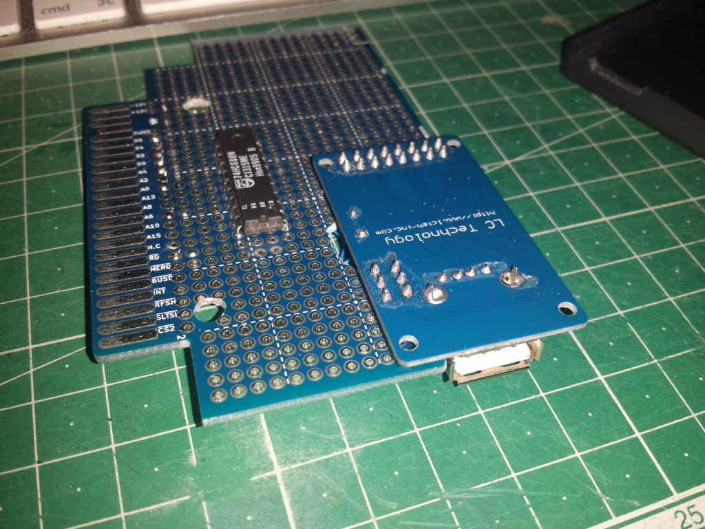
Last weekend I can not wait any longer, the prototypes on PCB were taking longer than I had planned, so I decided to mount a prototype wired to start testing on other computers. The first prototype I did was not complete, I left the EPROM out of the prototype, since I could use a board I already had to mount the EPROM, thus saving me the 28 connections and I could test the circuit quickly.
#3, PCB prototype
With Kicad I have designed the printed circuit, for the routing of the tracks I have used Freeroute, so that I have saved a good time working with the automatic routing (I understand that the result is not “ideal”)
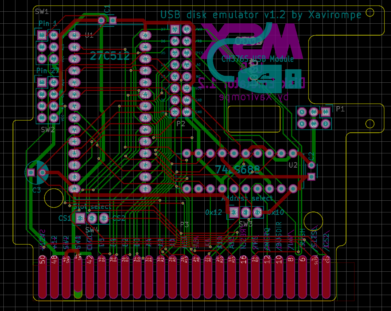
I have to say: I like the 3D visualization of Kicad !!!!! Yeah !!!
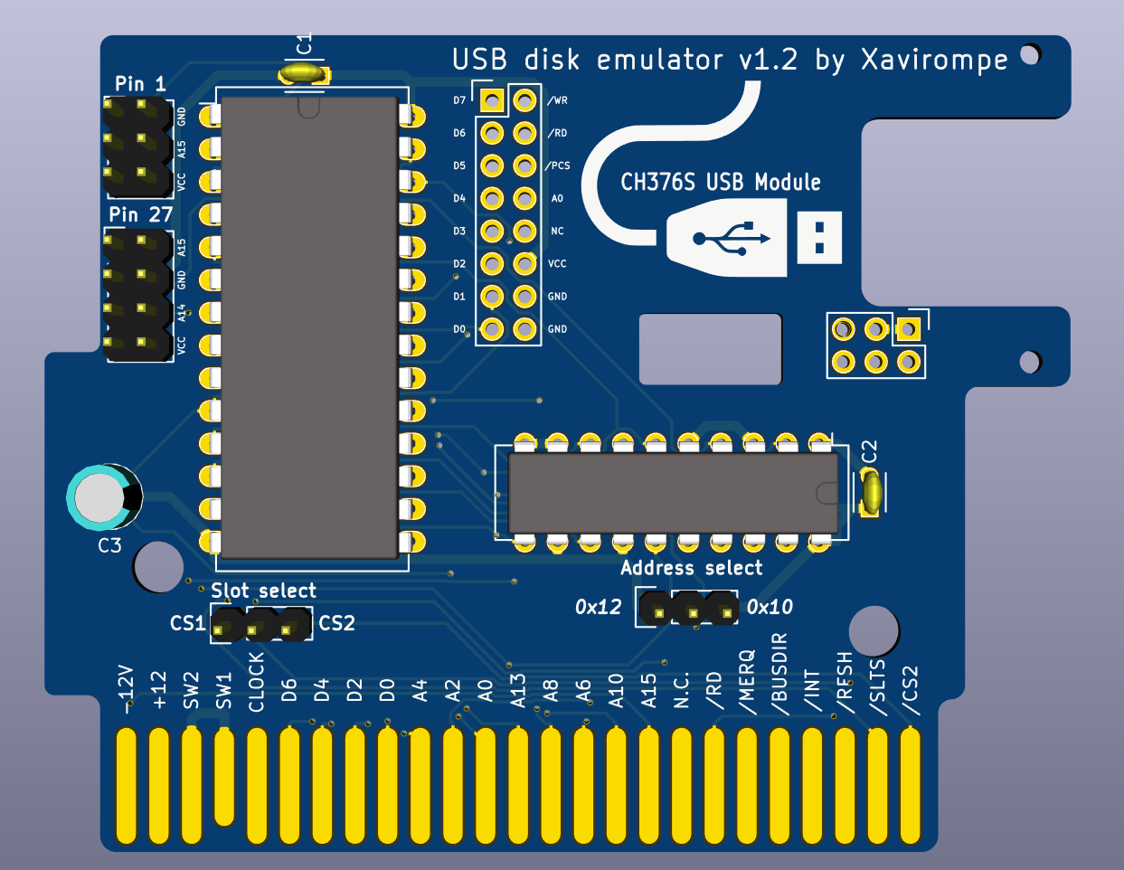
About the “absurd” shape of the PCB, the reason is that at the time of design had no more cartridges than a couple of indescomp, which are very complicated … (I put a photo below ..)
Finally, to arrive this morning (Monday, November 21, 2016)
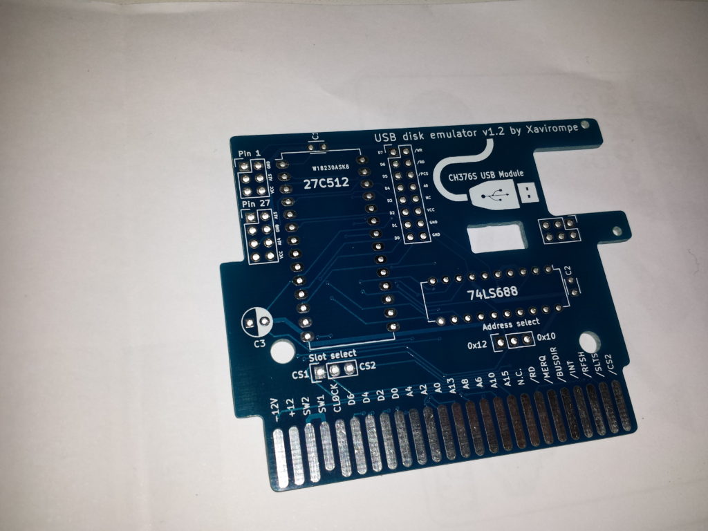
During assembly of prototype # 2 I discovered an “error” in the schematic, by mistake the line A5 is the one that marks the base address instead of the A4, that means that I had anticipated that the port address would be 0x10 (16) and ended up being 0x20 (32). It remains pending to test if it will work correctly in that port, and investigate the affectations or incompatibilities that may have.
Also it seems that there is a defect in the print, so the MSX logo has not been good 🙁 (I already complained to PCB way)
Arg !!!!!!!
I want to get home (now I’m in the office) to assemble and see if it works and fits correctly ..
#3.2 More test, proto “Monster”
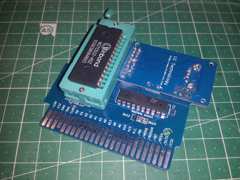
I confirm that it can work on ports 32 to 35, touching the source code and changing the original value to the “new”. I say it “works” on my test computer, which now is an HB-75P, as it has an expansion bus connection on the back, and allows me to insert this “monster” seamlessly, as you can see In the photos, has a ZIF socket, which is perfect for testing software changes without damaging the EEPROM.
And I’m still making corrections to improve rookie drive functionality.
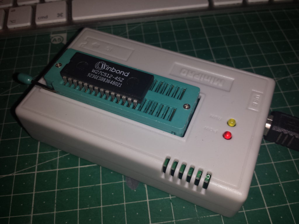
As a memory ROM I am using a Winbond w27c512 EEPROM, which I can burn thanks to the programmer “MiniPro”, fantastic for price and functionality, obviously it is a very basic programmer, but it fulfills the mission perfectly, highly recommended:
#2.2 Nice and upgradeable prototype
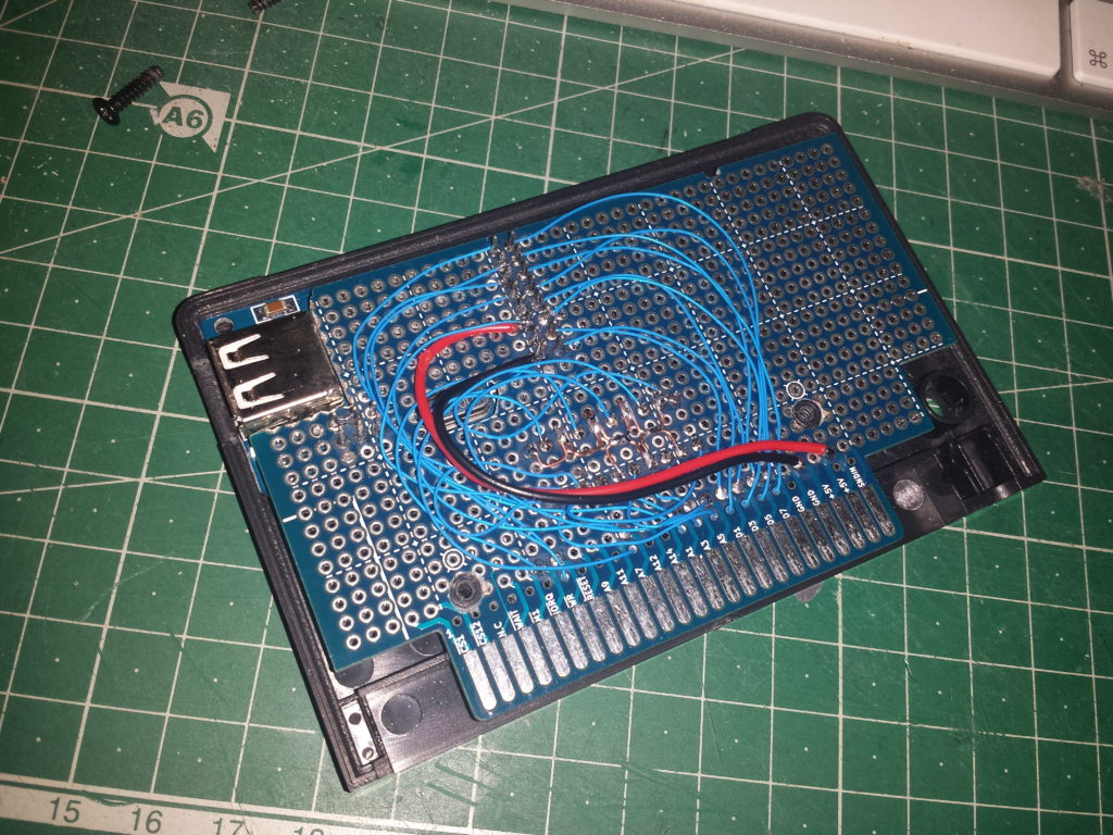
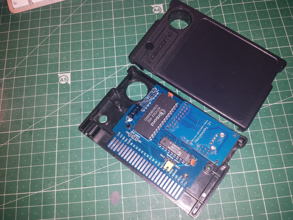
The moment of truth is near, there are only a few days left for RU # 50, and I work hard to be able to show my “cartridge”, so I decided to finish the work I started with the prototype # 2, which needed a second cartridge with the Eprom. After a few hours of insomnia, I got it !! The result is not 100% elegant, but gives a pretty rough idea of what a finished version would look like.
As seen in the image, the Eprom is accessible for extraction, it is possible to update its content, since it is mounted on a DIP socket, instead of being soldered directly to the PCB.
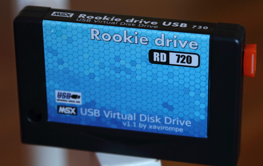
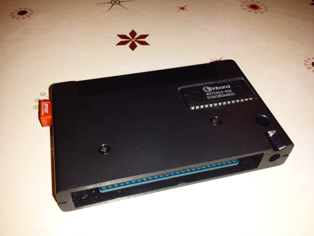
That’s how the cartridge looks from the front:
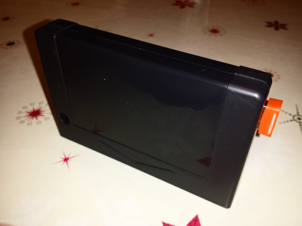
Here you have the look of the cartridge with its label: